Bragg Equation
BRAGG'S LAW --
HOW CRYSTALS AFFECT THE SCATTERING OF X-RAYS
The following is true and useful for all light (and electrons (EM) and neutrons). But, the development we will take will direct us toward 3-dimensional crystal diffraction of x-rays with only passing comments about fiber diffraction.
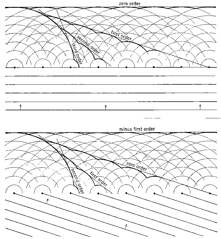
Now we consider the result of taking our scattering unit (an atom, or a molecule) and repeating it regularly in space. We must use our methods of combining waves to appreciate how the scattered light from multiple points combines to form a resultant wave. (Refer to the earlier section: “Vector Notation for Waves”.) A wave front can be considered to be made up of component individual rays. (Later, there is a diagram that shows how diffraction occurs when a wave front encounters an array of scatterers.)
Diffraction from a row of molecules
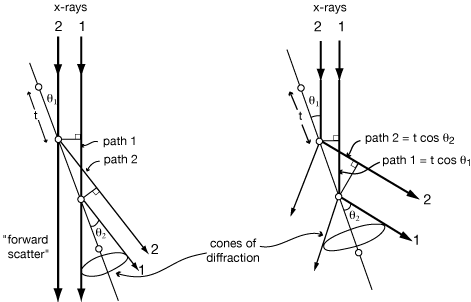
The incoming ray is in phase with itself, and in general the diffracted ray will be in phase with itself if all of the component rays’ travel paths differ in length only by an integral number of wavelengths.

|
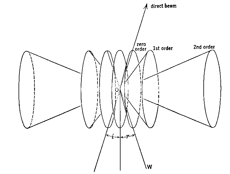
If θ1 = θ2, then path difference is zero. Zero-order diffraction (zero path length difference) is independent of d |
If d•cos(θ1) - d•cos(θ2) = nλ, then scattered rays are in phase. Higher order diffraction (finite path length difference) is dependent on d. |
SHARPNESS OF DIFFRACTION MAXIMA
So far we have only considered conditions for diffraction maxima (where scattered rays are exactly in phase.) For a row of 2 or 3 atoms, if the path lengths are just slightly wrong then the intensity of the diffracted beam is just slightly less than maximum, so the distribution of scattered x-rays would vary smoothly from a maximum at the in-phase angle to a minimum in-between.
But consider the case of zero order diffraction from a very long row of atoms:
If θ1 is just slightly smaller than θ1, then path 2 is shorter than path 1 by Δ = tcos(θ1) - tcos(θ2).
Likewise, path 3 is shorter than path 1 by 2Δ = 2tcos(θ1) - 2tcos(θ2),
and path 3 is shorter than path 1 by 3Δ = 3tcos(θ1) - 3tcos(θ2), and so on.
If ray 2 is only 1° out of phase with ray 1, then ray 181 will be 180° out of phase with ray 1. Furthermore, ray 182 will be 180° out of phase with ray 2, ..., and they will all cancel each other.

For a real crystal with 104 to 106 atoms in a row, cancellation is complete for even slightly incorrect angles, giving extremely sharp diffraction maxima (spots.) In fact, the spots on an x-ray photograph are somewhat smeared out because of the size of the x-ray source, the size of the crystal, the mosaic character of the crystal, and the spectral dispersion of the x-rays; but in spite of all that, the spots are still quite small and sharp.
DIFFRACTION FROM A TWO-DIMENSIONAL GRID OF ATOMS

|
Path difference between ray 1 and ray 2 is 2δ. If 2δ = nλ, then rays will be in phase. δ = d sin(θ), so Bragg's Law λ = 2(d/n)sin)θ) Where d is the distance between repeating units measured perpendicular to the A-A rows (planes in 3D), and d/n is the distance between Bragg Planes which cut that d into n equal intervals. |
This can also be thought of as the intersection of a zero-order diffraction cone from row A-A with a higher-order diffraction cone from row B-B. (This generalizes to the third dimension.) Intersections of cones give straight lines, so that diffraction from a grid is in discrete rays Higher order diffraction (finite path length difference) is dependent on d. |
Consider the case where the grid of atoms is non-orthogonal:

distances ε are all equal, and the path difference between rays 1 and 2 is still 2δ = 2dsinθ
In the general case, therefore, the d in Bragg’s Law is the perpendicular distance between planes, not the distance between atoms.
Thus for diffraction in a particular direction (defined by the normal to the “Bragg planes”), it is the projected distance between scattering atoms along that direction, not the raw distance between atoms, that determines the relative phases.
For instance, the diffraction pattern from the so-called “alpha” form of some proteins implied regular spacing between residues as well as a helical arrangement. However, polypeptide models that arranged the atoms directly in line along the helix axis failed to explain the details of the diffraction pattern. Linus Pauling proposed a compact model that did not have the atoms in line along the axial direction and he pointed out that this would still diffract! With this in mind, Max Perutz showed that his hemoglobin crystals contained a-helices -- which in turn comfirmed Pauling’s model. (But they did not at that time have enough information to know whether it was right-handed or left-handed!)
DIFFRACTION FROM 3-D ARRAY
If the x-rays are in the plane of the page in the diagrams above, then the condition can be generalized to three dimensions by visualizing a set of identical diagrams parallel to the page above and below. Rays scattered from all the atoms in any one diagram have been shown to be in phase, and since the path lengths are identical for any two corresponding atoms on different diagrams, all the rays from the entire three-dimensional array are in phase when Bragg’s Law is satisfied.

Restricted ray from single Bragg plane: direction limited and θi= θr, i.e mirror reflection; then deeper layers restrict θ.
Bragg planes are ⊥ to “d” ; if t of cell at angle α then:
![]()
This may look rather special but when diffraction conditions are satisfied one can always describe these conditions in terms of “Bragg planes”.
3-D lattice constrains diffraction to be in single beams, so can always draw diffraction on a 2-D diagram:
![]()
A diffracted “ray” is produced in the direction of the arrows, as a beam whose cross-sectional area is approximately the size of the crystal as seen from that direction.
The lattice limits when diffraction can occur, however, the relative intensity is determined by the relative intensity scattered from the molecule in that particular direction.
Download:
![]() PS-Bragg-Law-Limits.pdf(30KB)
Problem for this section
PS-Bragg-Law-Limits.pdf(30KB)
Problem for this section
DEFINITIONS
Scattering \'skad-er-ən\ :
Electrons in the path of an x-ray wave are set into forced vibrations by the periodically changing electric field of the x-ray wave passing by. These oscillating electrons are themselves sources of x-ray waves. This forced oscillation is of the same frequency as the incident x-ray wave, and the emitted x-ray waves are thus of this same frequency. By this interaction the electrons are said to scatter the original x-ray wave.
Diffraction \də-'frak-kshən\ :
Cooperative combination of scattered waves. This can occur if the scattering points are arranged in space in some regularly repeating manner. In certain directions with respect to the incident wave and the array of the scatterers, the scattered waves will combine constructively.
This can be used to increase the amount of scattered radiation to a point where meaningful measurements can be made. This application is used in crystallography; for, in our case, the study of “globular” proteins and nucleic-acids.
Conversely, the existence of a diffraction pattern and its characteristics can be used to detect and deduce something about a repeating structure. This aspect is exploited in the case of fibers, fibrous structures, and other extended polymers.


THE APPEARANCE OF THE DIFFRACTION PATTERN
The 2D crystal shown here has repeats t1 and t2 at right angles to each other. As we saw earlier, this perpendicular relationship is not necessary, but sure makes it easier to think about. In any case, d1 and d2 are the perpendicular distances between the rows. t1 and t2 define the repeating unit of the crystal, a.k.a. the unit cell. In these examples where the Bragg Planes run along the unit cell edges, the Bragg Planes of 1st order reflections span the unit cell, while the Bragg Planes of 2nd order reflections cut the unit cell in half (see below).

|
1st order: |
d2 = t2 |
2nd order: d3 = t1/2 = d1/2 |
If a piece of photographic film is put in place to intercept the x-rays, then it gets a mark at “0” from the direct beam and a spot at “P” from the diffracted (reflected) ray.
If d2 > d1 then θ2 < θ1 for diffraction to occur.
Notice that the distance O-P is approximately proportional to θ and inversely proportional to d. Spots far out from the center of the film come from planes that are quite close together in the crystal.
This reciprocal relationship between the spacings d in the crystal and the distances O-P in the diffraction pattern gives visible meaning to the term “reciprocal space” used to describe the diffraction pattern. Of course, that same reciprocal relationship is stated by Bragg's Law.
DIFFRACTION AS A PROBE FOR SPACINGS WITHIN A CRYSTAL
Diagrams are those above but with a square atom halfway between the round atoms that are spaced at distance d1.

lst order reflection #1 is weak because for that solution of the Bragg equation - with d1 being the distance between planes of atoms with 1 λ scattering path difference - the square atoms scatter 180° out of phase from the round ones.
lst order reflection #2 is strong because for that solution of the Bragg equation - with d2 being the distance between planes of atoms with 1 λ scattering path difference - the square atoms scatter in phase with the round ones, since they are both on the same planes.
2nd order reflection #1 is strong because for that solution of the Bragg equation - with d1' being the distance between planes of atoms with 1 λ scattering path difference = the square atoms scatter in phase with the round ones. (The way of uniquely indexing this reflection implies d1’ = d1/2).
As one travels along the normal direction from plane to plane, there is one phase clock revolution for each λ scattering path difference, n times across the repeating unit of the crystal.
Download:
![]() PS-3Planes-3Spots.pdf(70KB)
Problem for this section
PS-3Planes-3Spots.pdf(70KB)
Problem for this section
